1.1.9. Cabled Range Extender (CRE)

1.1.9.1. Introduction
The CRE board set is comprised of an A end plus a B end. The former is connected to the end of the local sensor chain and provides an RJ45 connector for extending the chain via twisted pair (CAT5/CAT6) cabling.
The B board connects to the other end of the twisted pair cabling and enables sensor modules to be connected remotely.
The boards transition from single-ended I2C to differential signalling, and then back again. In addition to which the CRE-A boosts the power supply voltage so as to account for any cable losses, with the CRE-B board providing voltage regulation for the remotely connected sensors.
Warning
Sensors which use plain GPIO for interfacing may not be used at the remote end.
1.1.9.2. CRE-A schematic diagram

1.1.9.3. CRE-A theory of operation
The ESDK-CRE-A board converts the single-ended ESDK I2C bus into two differential signals for transmission down a CAT5e/CAT6 cable using an NXP PCA9615 driver plus bias network comprising of six resistors. TVS diodes are present on the differential side to help reduce the risk of ESD related damage.
A DC-DC boost converter takes a 5V supply and produces 12V at up to 0.3A for transmission down the signal cable to help reduce losses. This utilises a Texas Instruments LMR62014 boost converter controller with integrated MOSFET switch, simplifying the design. A polyfuse is present on the 12V output to help reduce the risk should an inadvertent short circuit happen.
The right-hand facing female header is instead replaced with a standard RJ45 connector to enable the use of straight through network cables.
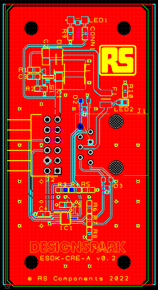
1.1.9.4. CRE-A board layout
1.1.9.5. CRE-B schematic diagram
1.1.9.6. CRE-B theory of operation
The ESDK-CRE-B board performs the inverse function of the CRE-A board — it converts the incoming differential I2C bus back into a single ended bus whilst also producing 5V and 3.3V sensor power supply rails. A matching NXP PCA9615 driver plus bias netowrk is used to convert the bus, plus ESD diodes on both differential and single-ended sides of the bus to help reduce the risk of ESD damage.
A Texas Instruments LMR12010 DC-DC buck converter with integrated switch first produces a steady 5V rail, which is then passed through a LD1117S33 linear regulator to produce 3.3V. A fuse is present on the 5V rail to reduce the risk of inadvertent short circuits.
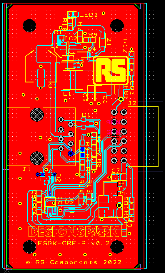
1.1.9.7. CRE-B board layout